32 Pin Connector Detail

Many of the figures are taken from P112 HYBRID VEHICLE CONTROL manual: http://static.hybrids.ru/files/OfficialToyotaInfo/RepairInformation/RepairManual/HV%20-%20P112%20Hybrid%20Vehicle%20Control.pdf
32 pin connector 🔌
This section will include a pin-by-pin investigation into the details of each of the 32 pin connector pins.
- –
Unused…
- GIVA : MG1 phase current V
- GIVB : MG1 phase current V
Current sensor pins. What voltage are they? How is current sensed?
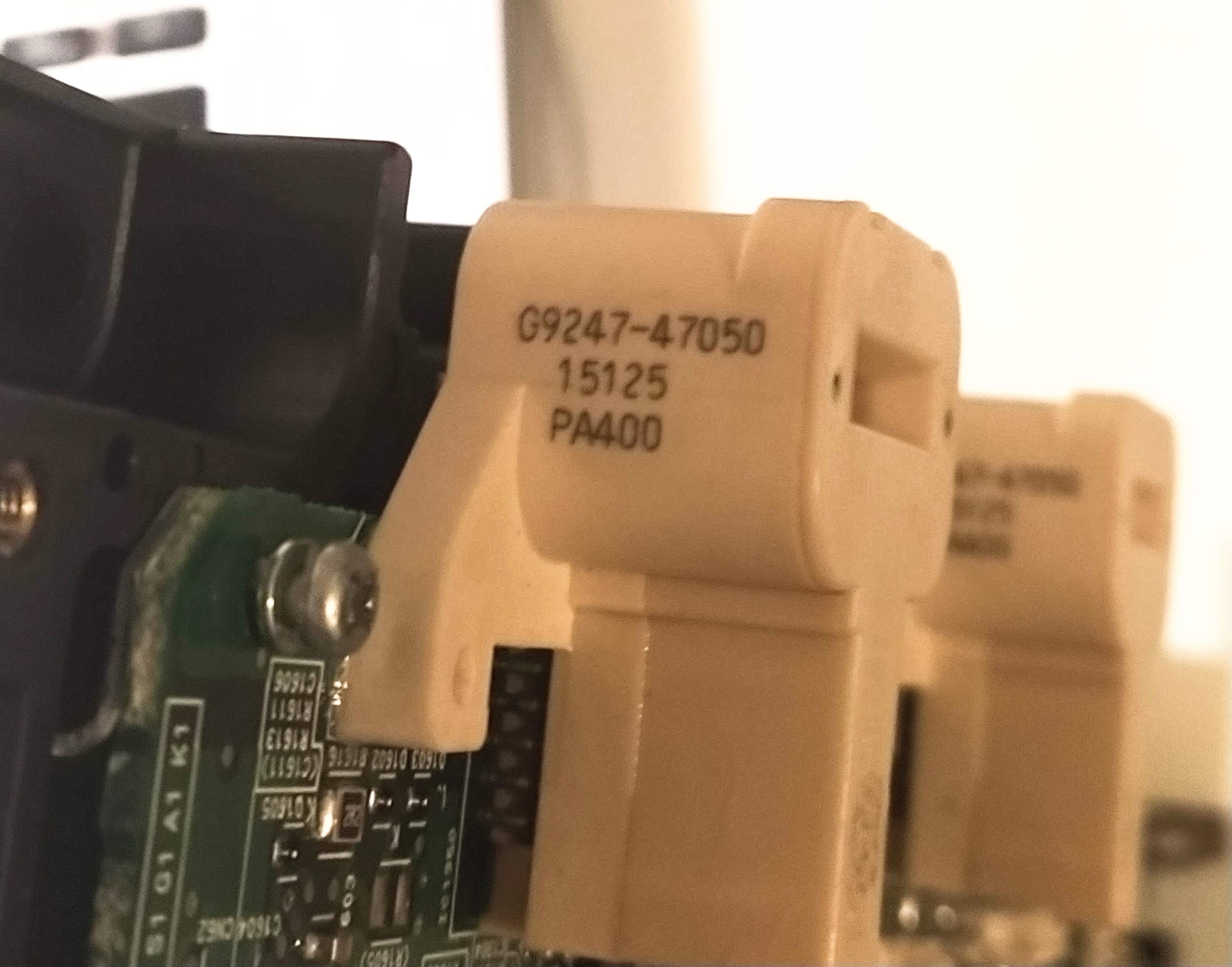
- G9247-47050
- Attached to the main inverter PCB with the phase bar passing through the centre
- Apparently they are hall effect sensors
- GUU : MG1 PWM U
- GVU : MG1 PWM V
- GWU : MG1 PWM W
Can these control the IGBTs when the shutdown pin (pin 14) is turned off? What voltage PWM? What frequency can be used?
- MIVA : MG2 phase current V
- MIVB : MG2 phase current V
Refer to pins 2 and 3
- MUU : MG2 PWM U
- MVU : MG2 PWM V
- MWU : MG2 PWM W
Refer to pins 4, 5 and 6
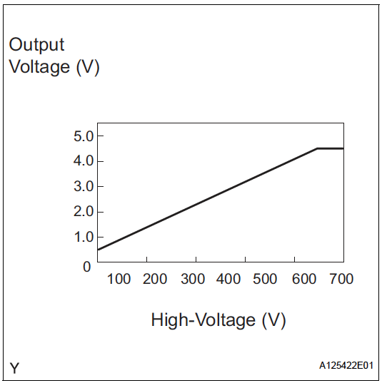
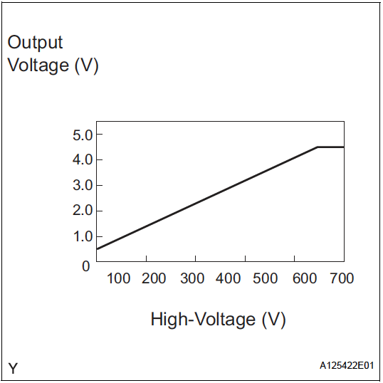
- VH : Inverter capacitor voltage ✅
- VH = 0.5 + 1/100
- High voltage after boosting (inverter supply voltage)
- Ranges from 0 to 5V
- Comes from boost converter controller
- Referenced against GCNV
- (similar to VL pin 15)
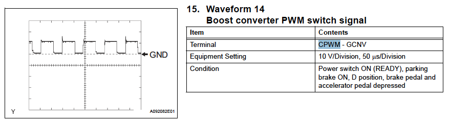
- CPWM : Boost converter switch signal ✅
- Nominal switching frequency: 2khz (10khz shown in figure)
- Maximum switching frequency: 25khz
- Voltage: 0 to 10V PWM (centred at 5 V)
- Referenced against GCNV
- Connected to Boost Controller (Blue wire)
- CSDN can turn off the half-bridge completely
- GSDN : MG1 shutdown
Maybe swapped with pin 20 (CT)???
- Input to inverter from HV control ECU
- Tie to logic ground to turn on (below 0.7) [to be tested!]
- Tie to 5.1V - 13.6V to shutdown [to be tested!]
- Referenced to GINV
- “Upon receiving a motor gate shutdown signal from the HV control ECU, the inverter forcefully stops the operation of the MG2 by turning OFF the power transistors that are actuating the MG2.” -
- VL : Boost converter input voltage ✅
- VL = 0.5 +1/100(Orange wire with spade terminal – CN screw terminal)
- High voltage before boosting (battery voltage)
- Ranges from 0 to 5V
- Comes from boost converter controller
- Referenced against GCNV
- Connected to Boost Controller (Purple/White)
- (similar to VH pin 12)
- GINV : Inverter ground ✅
- Use for any pins referenced to GINV from HV system manual
- Connected to Boost Controller (Black wire)
- –
Unused…
- GIWA : MG1 phase current W
- GIWB : MG1 phase current W
Refer to pins 2 and 3
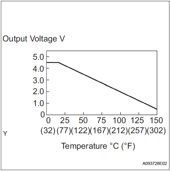
- CT : Boost converter temperature sensor ✅
Maybe swapped with pin 14 (GSDN)??? - It seems so
- Varies from 0 to 5V
- 4.5V = less than 205°C
- 0.5V = 150C
- Min.: -50°C, Max.: 205°C
- Referenced against GCNV
- (found on page HV-397)
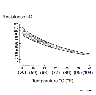
- GIVT : MG1 inverter temperature
- Min.: -50°C, Max.: 205°C
- The lower the motor temperature, the higher the resistance of the thermistor
- Conversely, the higher the temperature, the lower the resistance.
- (found on page HV-189)
- “The power voltage of 5 V is supplied from the MMT terminal of the HV control ECU to the No. 1 motor temperature sensor via resistor R. Because resistor R and the No. 1 motor temperature sensor are connected in series, the resistance changes with the changes in temperature of the motor, which causes the MMT terminal voltage to also change.”
- GFIV : MG1 inverter fail
Where does the error come from?
- MIWA : MG2 phase current W
- MIWB : MG2 phase current W
Refer to pins 2 and 3
- MSDN : MG2 shutdown ✅
Refer to pin 14
- MVIT : MG2 inverter temperature
Refer to pin 20 and 21
- MFIV : MG2 inverter fail
Refer to pin 22
- OVH : Overvoltage ✅
- Connected to Boost Controller (Pink)
- Connected to OVH from inverter as well
- NORMAL: 5.3 to 7.3 (5V to run)
- ABNORMAL: 1.9 to 2.9 (Ground for fault)
- “If the motor inverter detects a circuit malfunction or over-voltage, the inverter transmits this information to the OVH terminal of the HV control ECU via the motor inverter over-voltage signal line. The HV control ECU monitors the motor inverter over-voltage signal line to detect the malfunction.”
- CSDN : Boost converter shutdown signal ✅
- Input to inverter from HV control ECU
- Tie to logic ground to turn (below 0.7)
- Tie to 5.6V or more to shutdown
- Referenced against GCNV
- Connected to Boost Controller (Brown wire)
- “Upon receiving a boost converter gate shutdown signal from the HV control ECU, the boost converter forcefully stops the operation of the boost converter by turning OFF the power transistors that are actuating the boost converter.”
- FCV : Boost converter fail signal ✅
- Connected to Boost Controller (Red/White wire)
- NORMAL: 5.3 to 7.7 (5V to run)
- ABNORMAL: 1.9 to 3.0 (Ground for fault)
- “If the boost converter has a circuit malfunction, or internal short, or overheats, the boost converter transmits this information to the FCV terminal of the HV control ECU via the boost converter fail signal line. The HV control ECU monitors the boost converter fail signal line and detects a malfunction.”
- OVL : Boost converter over voltage signal ✅
- Connected to Boost Controller (Blue/Pink wire)
- NORMAL: 5.3 to 7.7 (5V to run)
- ABNORMAL: 1.9 to 3.0 (Ground for fault)
- “If the boost converter detects a circuit malfunction or over-voltage, the boost converter transmits this information to the OVL terminal of the HV control ECU via the boost converter over-voltage signal line. The HV control ECU monitors the boost converter over-voltage signal line and detects a malfunction.”
- GCNV : Boost converter ground ✅
- Use for any pins referenced to GCNV from HV system manual
- Connected to Boost Controller (Black wire)
Boost Converter Module
https://nicjam.es/projects/how-to-turn-on-the-gen2-prius-boost-converter-module/
PM400JA120
- Voltage bus signal scaled from 0 to 5V
- Temperature sensor
- Isolated high-side supply
Pinout:
- –
- –
- CT? (Green/Red) - Seems to be connected to GSDN pin on connector A
- VL [scaled] (Purple/White)
- OVH (Pink) - also connected to the inverter
- CPWM (Blue)
- GINV (Black)
- IGCT (Red)
- Battery Connection (Orange with spade)
- –
- –
- OVL (Blue/Pink)
- FCV (Red/White)
- GCNV (Black)
- CSDN (Brown)
- –
Converter tests
Conditions:
- Main board unplugged
- 12V powered from external power supply
- GINV and GCNV are connected
- All other pins are connected through the 32 pin connector
- CL, CP and CN pins are disconnected
Tests:
- Is the CT pin who it says it is? (should be 4.5V)
- Test shutdown pin
- Does PWM pin change charecteristics
- Do measurement pins change
- Test PWM pin
- Place high and low voltages on pins
- Place PWM signal on pin
- Test VL pin
- Place sample of known voltage on output
Results:
NO PWM
- CSDN tied to ground
- IGCT to 12V
- All grounds connected together
- OVH tied to 5V
Result:
- CT = 4.75V
- OVL = 15.71V
- FCV = 15.72V
PWM connected to ground
- CSDN tied to ground
- IGCT to 12V
- All grounds connected together
- OVH tied to 5V
Result (diode test mode):
- 0.407V from CL to CP
- Open from CL to CN
PWM connected to 12V
- CSDN tied to ground
- IGCT to 12V
- All grounds connected together
- OVH tied to 5V
Result (diode test mode):
- Open from CL to CP
- 0.407V from CL to CN
Shutdown pin ON
- CSDN tied to 5V
- CPWM tied to GND or 12V
- IGCT to 12V
- All grounds connected together
- OVH tied to 5V
Result (diode test mode):
- Open from CL to CP
- Open from CL to CN
No power
Result (diode test mode):
- Open from CL to CP
- Open from CL to CN
PWM current
- CSDN tied to ground
- IGCT to 12V
- All grounds connected together
- OVH tied to 5V
Inverter / Converter tests
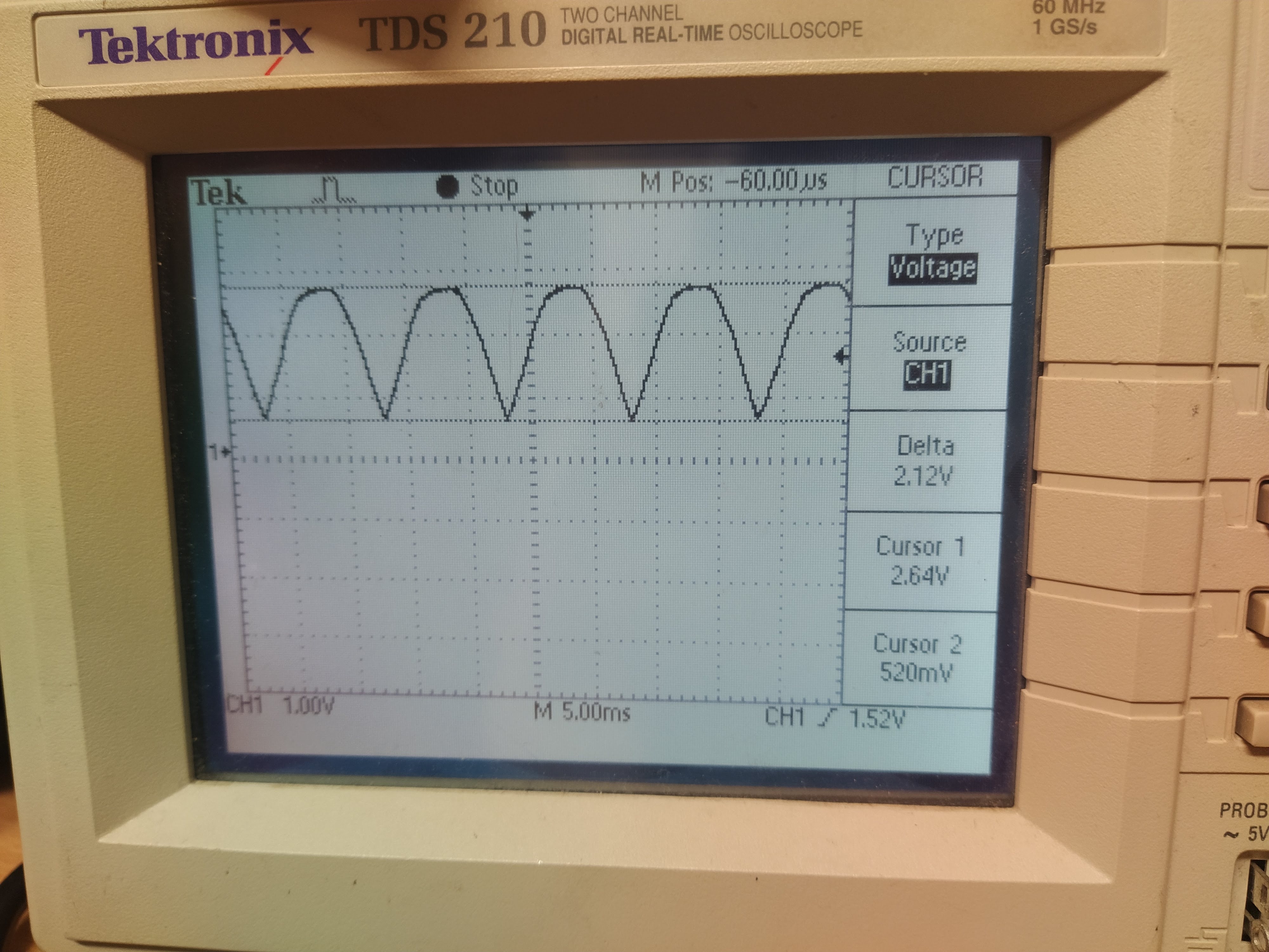
Test the rectified waveform using the scaled VH pin
- Live was connected to the V phase of MG2
- Neutral was connected to the W phase of MG2
- Earth was connected to the inverter case
- IGCT 12V supply is applied
- VH is shown in the figure below. The scaled voltage VH = 0.5 + 1/100(the rectified voltage)