Charger Board Update

ADC Measurements
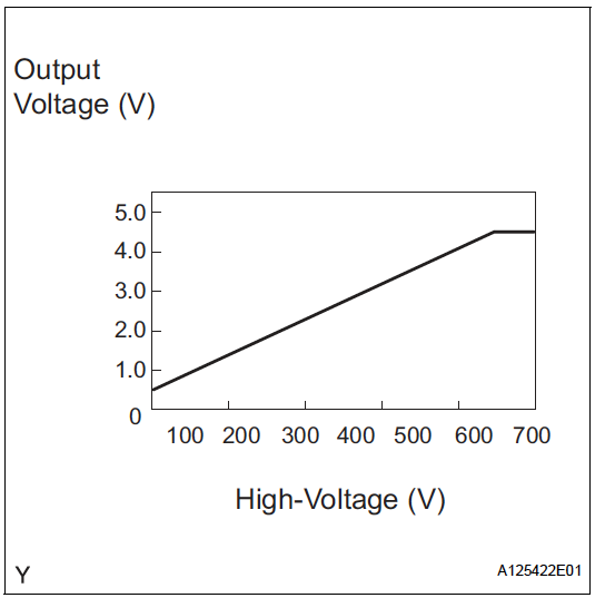
The high voltages on the inverter can be measured using the isolated voltage measurement signals. The following formula can be used to calculate the actual voltage from the scaled signal:
Vc = (Vmeas - 0.5V)*100
The bare minimum high voltage resolution I would like is 0.1V.
If the maximum voltage is 500V, 500V/0.1V = 5000 levels are required to achieve the required resolution.
If the maximum scaled voltage is 5V, the smallest detectable voltage would then be 5V/5000 = 0.001V. Therefore, any noise would have to be smaller than this voltage.
The minimum number of bits is then log2(5000) = 12.29, so a 13-bit ADC would have the minimum allowable bit resolution.
The ADS1115 is a 16-bit ADC which should be able to suit the purposes of these signals.
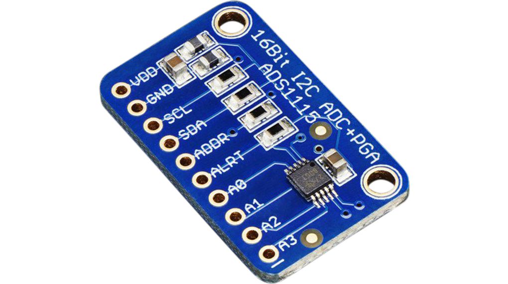
Since there are 4 inputs to the ADS1115 board, 4 of the analog values can be read and 2 can be monitored in a different way. VH, VL, GIWA and GIVA are sent to the ADS1115 and CT and GIVT are monitored using a comparator and an interrupt.
Charging Procedure
- Turn on HIGH side switch (0% converter PWM)
- Precharge the capacitor
- Close main contactor, once capacitor voltage has settled
- Increase PWM until capacitor is at the set voltage
- Connect the mains
- Adjust voltage until no current flows
- Adjust voltage to keep constant charging current
- Enter constant voltage stage when within certain range of charged battery voltage
- Disconnect mains
- Reduce PWM slowly
- Open contactors
The full charging procedure can be controlled with a finite state machine. An update function can be run in order to check for events and update the state machine.
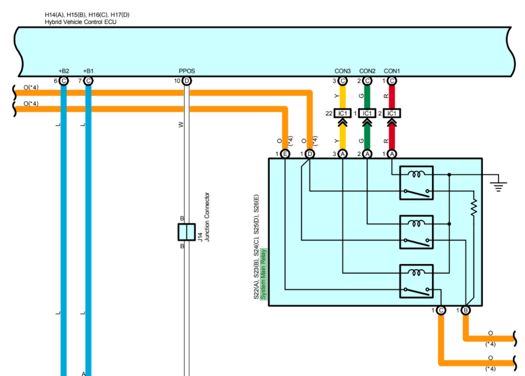
Relays
There are a total of 5 relays needed for the charger. 2 main contactors each for the battery and mains and an extra precharge resistor for the battery. The battery relays are contained within the battery unit and accessible to the hybrid ECU. However, the two contactors for the mains will have to be added.
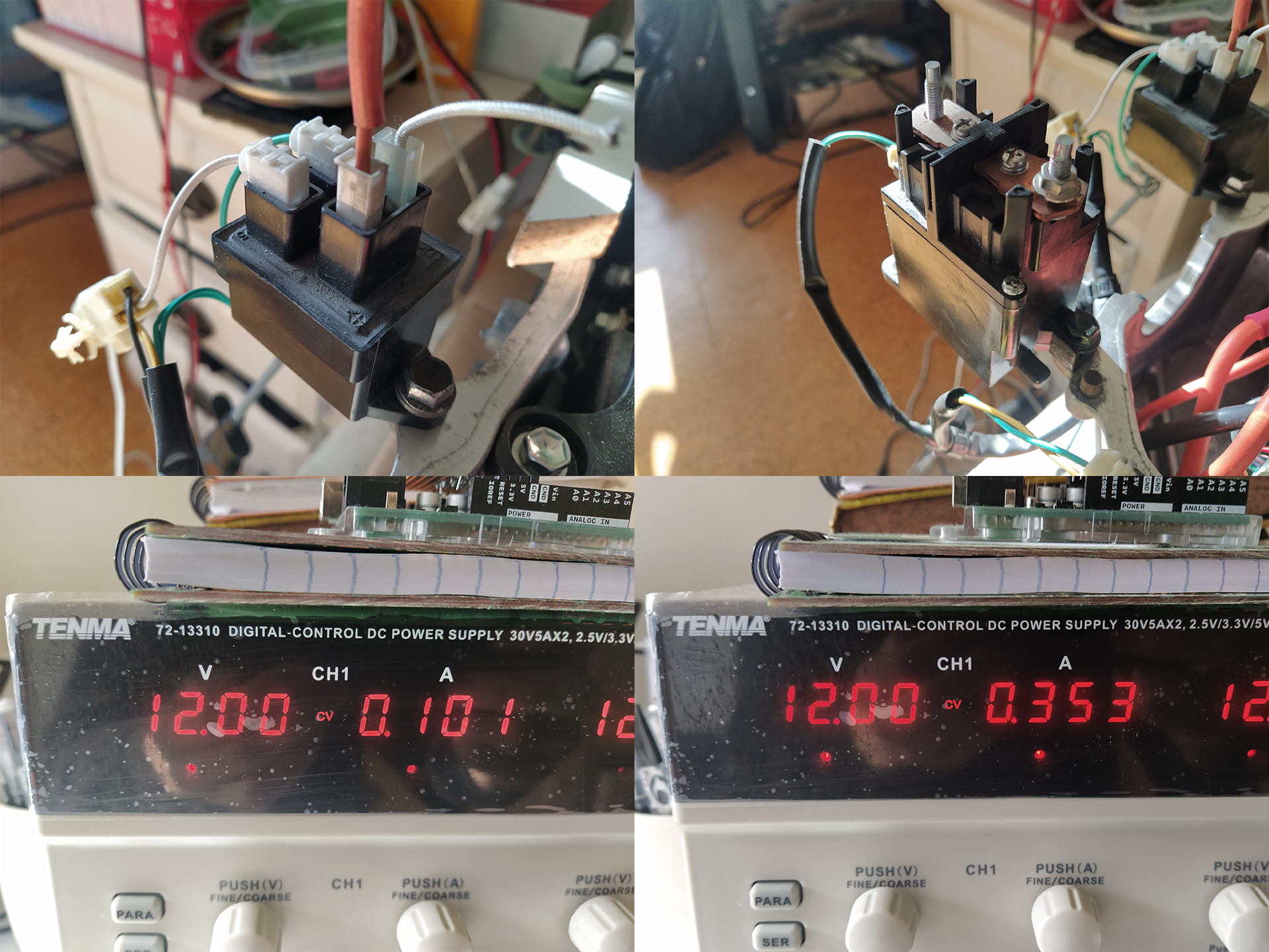
As you can see from the figure, the small relay pulls 101mA and the large relays pull 353mA. Regular 2n3904 bipolar transistors can handle 200mA constant current according to their datasheet, so a darlington pair can be used for the larger contactors and a 2n3904 can be used for the precharge relay.
These relays can be controlled from the H16 Hybrid ECU connector, which is why the charging controller board should be placed in between the hybrid ECU and inverter, instead of being connected directly at the inverter.
Hybrid ECU connections
The hybrid ECU has 4 connectors A (H14), B (H15), C (H16) and D (H17). Detail of each of the connectors follows. Any pin names in bold correspond to pins that are needed for the charge controller.
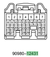
H14 is a 31 pin 90980-12431 connector that is connected to the power source controller, CAN bus, transponder key, cruise control, shift lever, airbag and accelerator position sensor.
- GND1: Chassis Ground
- GND2: Chassis Ground
- ST2: (Power Source Control ECU and combination meter)
- TC: (Data link connector)
- IGSW: Ignition switch (Transponder Key Computer)
- CANH: CAN High
- CANL: CAN Low
- CCS: Cruise Control Combination Switch
- E2X2: (Shift Lever Position Sensor)
- E2X1: (Shift Lever Position Sensor)
- VCX2: (Shift Lever Position Sensor)
- VCX1: (Shift Lever Position Sensor)
- IMI: (Transponder Key Computer)
- SPD1: Speed? (Power Source Control ECU)
- ABFS: (Airbag Sensor)
- VCX3:(Shift Lever Position Sensor)
- VSX3: (Shift Lever Position Sensor)
- VSX2: (Shift Lever Position Sensor)
- VSX1: (Shift Lever Position Sensor)
- IMO: (Transponder Key Computer)
- EP1: (Accel Position Sensor)
- RDY: Ready (Power Source Control ECU)
- VSX4: (Shift Lever Position Sensor)
- VCX4: (Shift Lever Position Sensor)
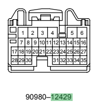
H15 is a 35 pin 90980-12429 connector that is connected to the inverter and stop light.
- ILK: Inverter interlock (Inverter)
- ST1-: (Stop Light Switch)
- STP: Stop (Power Source Control ECU and Stop Light Switch)
- BATT: 12V battery (IGCT Relay)
- MSDN MG2 Shutdown (Inverter)
- MUU: MG2 PWM U (Inverter)
- MVU: MG2 PWM V (Inverter)
- MWU: MG2 PWM W (Inverter)
- GWU: MG1 PWM W (Inverter)
- GVU: MG1 PWM V (Inverter)
- GUU: MG1 PWM U (Inverter)
- GSDN: MG1 Shutdown (Inverter)
- P1: Main switch (Main SW)
- MFIV: MG2 Inverter Fail (Inverter)
- MIVT: MG2 Inverter Temperature (Inverter)
- MIWB:MG2 Phase current W (Inverter)
- MIVB: MG2 Phase current V (Inverter)
- OVH: Overvoltage (Inverter)
- GIMV: (Inverter)
- ET1:TOINV (Inverter)
- STB: (Inverter)
- VN: VH capacitor voltage (Inverter)
- GIVT: MG1 Inverter Temperature (Inverter)
- MIWA: MG2 Phase current W (Inverter)
- MIVA: MG2 Phase current V (Inverter)
- GIWB: MG1 Phase current W (Inverter)
- GIWA: MG1 Phase current W (Inverter)
- GIVB: MG1 Phase current V (Inverter)
- GIVA: MG1 Phase current V (Inverter)
- GFIV: MG1 Inverter Fail (Inverter)
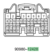
H16 is a 35 pin 90980-12428 connector that is connected to the battery relays, main relay, air con water pump relay, the boost converter, engine controller, accelerator position sensor and circuit breaker sensor.
- CON1: Battery precharge relay
- CON2: Battery positive relay
- CON3: Battery negative relay
- MREL: Main relay (IGCT Relay)
- WP: Air conditioning water pump relay (AC W/P Relay)
- +B2: Connected to +B1 12V (IGCT Relay)
- +B1: Connected to +B2 12V (IGCT Relay)
- GCNV: Converter ground (Inverter)
- CSDN: Converter Shutdown (Inverter)
- CPWM: Converter PWM (Inverter)
- NEO: (Engine control module)
- GO: (Engine control module)
- ITE: TOECU (Inverter)
- AS1: SIF+ (Circuit Breaker Sensor)
- ASIG: SIF- (Circuit Breaker Sensor)
- CLK: Clock (Inverter)
- FCV: Boost converter fail (Inverter)
- CT: Converter temperature (Inverter)
- OVL: Overvoltage (Inverter)
- NODD:
- VCP1: (Accel Position Sensor)
- VPA1: (Accel Position Sensor)
- EP1: (Accel Position Sensor)
- VL: VL boost converter voltage (Inverter)
- VLO:
- VCP2: (Accel Position Sensor)
- VPA2: (Accel Position Sensor)
- EP2: (Accel Position Sensor)
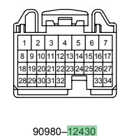
H17 is a 34 pin 90980-12430 connector that is connected to the transmission control ECU, power source control ECU, MG1 and MG2.
- PCON: (Transmission control ECU)
- PPOS: (Power source control ECU and transmission control ECU)
- MMT: (MG2)
- MSNG: (MG2)
- MSN: (MG2)
- GSNG: (MG1)
- GSN: (MG1)
- GCS: (MG1)
- GCSG: (MG1)
- GRFG: (MG1)
- GRF: (MG1)
- MMTG: (MG2)
- OMTG: (MG2)
- OMT: (MG2)
- MCSG: (MG2)
- MCS: (MG2)
- MRF: (MG2)
- MRFG: (MG2)