Prius High Voltage System Overview

Battery System Overview 🔋🔋🔋🔋🔌
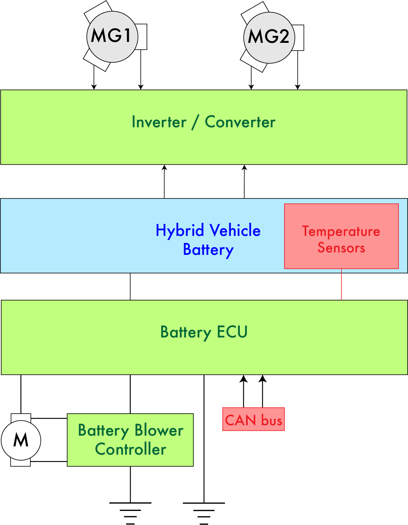
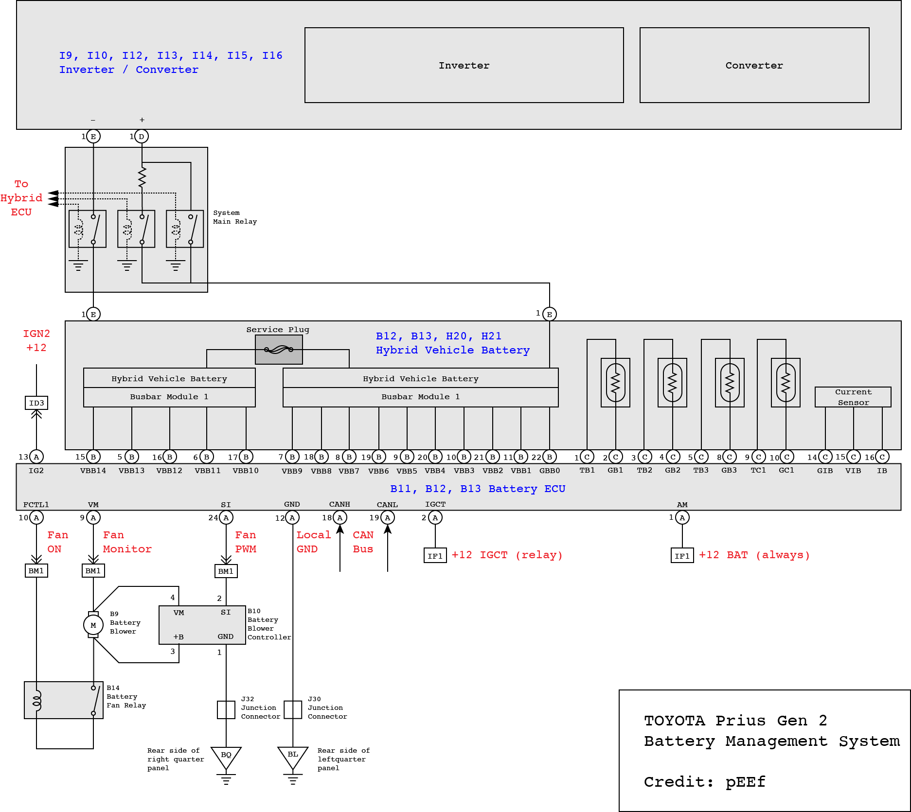
- Battery ECU : Effectively a Battery Monitoring System (BMS) that monitors the cell voltages and controls the battery blower (Battery ECU teardown by pEEf: https://priuschat.com/threads/battery-ecu-secrets-and-teardown-warning-geek-content.85987/)
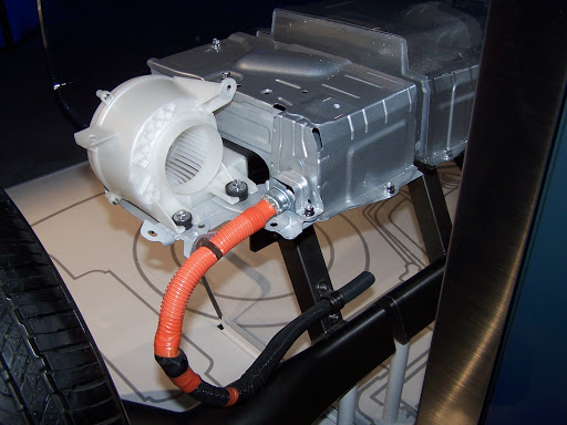
- Battery Blower : Used to cool the battery
- Battery Blower Controller : Drives the battery blower motor
- Traction Battery : The high voltage battery that drives the car
- Inverter / Converter : Converts between AC and DC power for powering the motors from the traction battery and charging the traction battery from the motors
- Hybrid vehicle control ECU : The main controller that coordinates the inverter/converter, ICE and battery
Battery 🔋
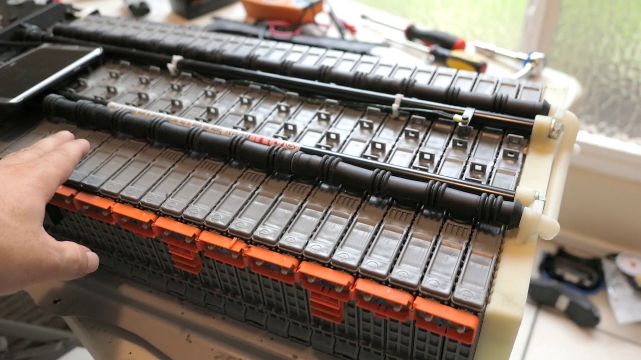
- High Voltage Traction Battery
The high voltage battery (also known as the traction battery) is a 201.6V NiMH battery composed of 28 modules (7.2V each), where each module is made of six individual 1.2-volt, 6.5 Ah Panasonic Prismatic NiMH cells. The 28 modules are connected in series to produce a total energy storage capacity of 1.310kWh (201.6-volts × 6.5 Ah).
Total voltage:           201.6V
Total energy storage:    1.31kWh
Number modules:          28
Module voltage:          7.2V
Module energy:           46.8Wh
Number cells per module: 6
Cell voltage:            1.2V
Cell energy:             7.8Wh
- Cooling System
Passive battery cooling and heating is accomplished through the metal case of the battery assembly pack, while a forced air cooling system with a blower motor and ducting system enables active cooling of the HV battery. The blower motor is driven by a blower motor controller which is controlled by the battery ECU.
- Low Voltage Battery
The 12V lead acid battery in the boot of the car. The low voltage battery is charged by the Inverter/Converter which gets its power from the traction battery.
Inverter / Converter 🌊 〰️
Functions:
- 2 inverters for MG1 and MG2
- Buck/Boost converter for battery charging
- 12V dc-dc converter
- Climate control AC inverter
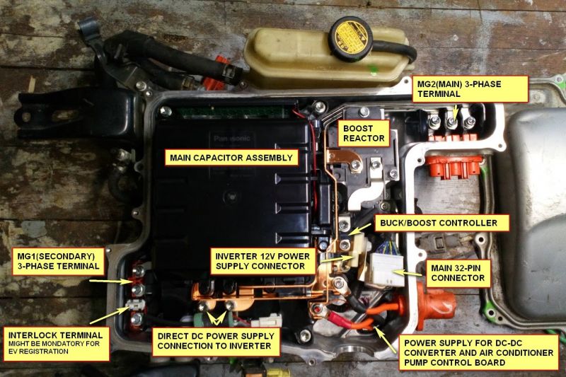
The MG1 and MG2 inverter units can be used either to drive the MG1 and MG2 motors or to use the motors to power a load (usually charging the battery). MG1 and MG2 are 3 phase synchronous motors with delta wound stators. The inverter takes three phase control signals from the Hybrid Control ECU which modulate the DC voltage from the boost converter in a sinusoidal-like pattern to drive the motors. The inverters can also rectify the motor voltage using the internal diodes.
The buck/boost converter is connected to the battery at one end, and the inverters at the other end. It is used to step up the battery voltage for driving the motors and for stepping down the motors voltage to charge the battery. It is controlled using the CPWM pin which takes a PWM signal to control the buck/boost action of the converter.
The 12V DC-DC converter is used to charge the auxiliary 12V lead acid battery from the traction battery and to run any other low voltage electronics.
An extra AC inverter is included to drive the pump for the climate control system.
32 pin connector:
- –
- GIVA : MG1 phase current V
- GIVB : MG1 phase current V
- GUU : MG1 PWM U
- GVU : MG1 PWM V
- GWU : MG1 PWM W
- MIVA : MG2 phase current V
- MIVB : MG2 phase current V
- MUU : MG2 PWM U
- MVU : MG2 PWM V
- MWU : MG2 PWM W
- VH : Inverter capacitor voltage
- CPWM : Boost converter switch signal
- GSDN : MG1 shutdown
- VL : Boost converter input voltage
- GINV : Inverter ground
- –
- GIWA : MG1 phase current W
- GIWB : MG1 phase current W
- CT : Boost converter temperature sensor
- GIVT : MG1 inverter temperature
- GFIV : MG1 inverter fail
- MIWA : MG2 phase current W
- MIWB : MG2 phase current W
- MSDN : MG2 shutdown
- MVIT : MG2 inverter temperature
- MFIV : MG2 inverter fail
- OVH : Overvoltage
- CSDN : Boost converter shutdown signal
- FCV : Boost converter fail signal
- OVL : Boost converter over voltage signal
- GCNV : Boost converter ground
Battery Monitoring System ⚖️🔋
The Battery ECU is the main control board for the battery. This controller keeps the state of charge (SOC) between approximately 40 and 80 percent (shallow cycling), where the average SOC hovers around 60 percent, allowing about 400 Wh of useful energy storage to capture energy The shallow cycling enables the hybrid battery to last tens of thousands of cycles, which translates into decades of use and in many cases more than 200,000 miles (320,000 km) of operation.
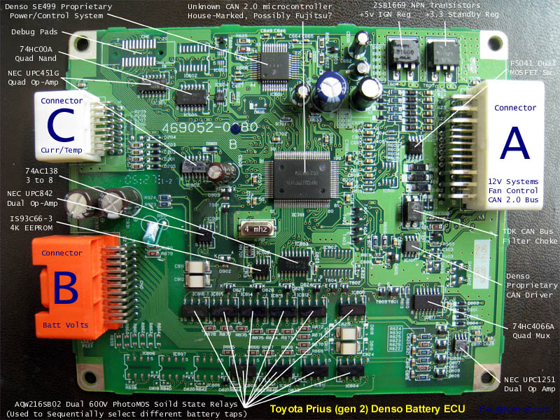
The shallow cycling means that the batteries cells do not need to be balanced. High precision matched cells are used so that they charge and discharge at the same rate and therefore maintain the same voltage over many cycles. Therefore the Battery ECU monitors the voltages of a group of modules, temperature and the battery blower system.