Plug-in Converter Board

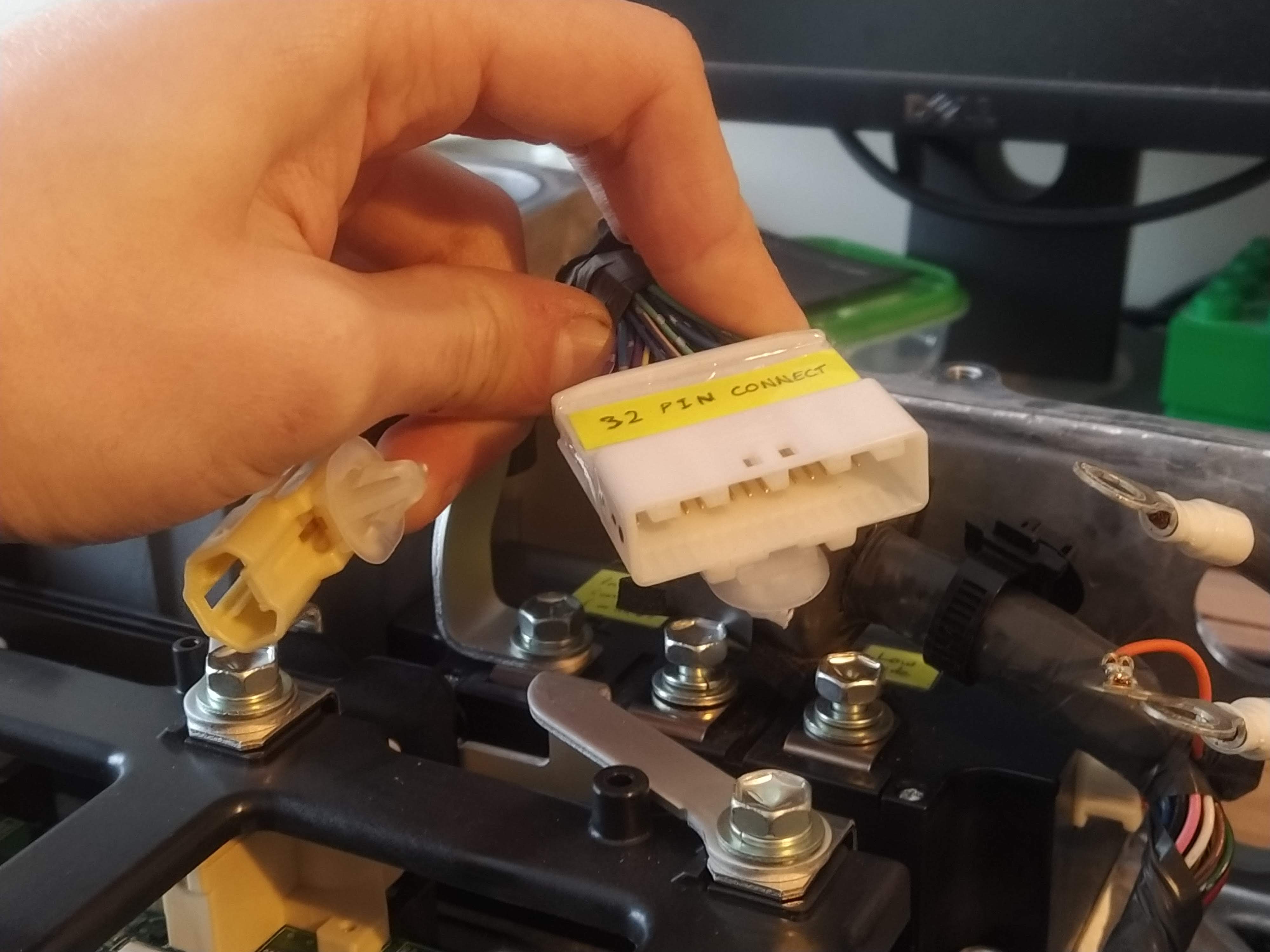
32 pin connector 🔌
The 32 pin connector enterring the prius inverter will be intercepted by the new conversion board. Another 32 pin connector will connect the new board to the inverter.
The male 32-pin connector that is attached to the hybrid ECU is number: 1318747-1 The female 32-pin connector that is attached to the inverter is number: 1318745-2
- Pass = connect directly to Hybrid ECU
- Monitor = pass the signal to the Hybrid ECU, and to the converter board
- Intercept = be able to connect and disconnect the signal from the Hybrid ECU and connect to circuitry on the converter board
- –
- Monitor : MG1 phase current V (GIVA)
- Pass : MG1 phase current V (GIVB)
- Pass : MG1 PWM U (GUU)
- Pass : MG1 PWM V (GVU)
- Pass : MG1 PWM W (GWU)
- Pass : MG2 phase current V (MIVA)
- Pass : MG2 phase current V (MIVB)
- Pass : MG2 PWM U (MUU)
- Pass : MG2 PWM V (MVU)
- Pass : MG2 PWM W (MWU)
- Monitor : Inverter capacitor voltage (VH)
- Intercept : Boost converter switch signal (CPWM)
- Intercept : MG1 shutdown (GSDN)
- Monitor: Boost converter input voltage (VL)
- Monitor : Inverter ground (GINV)
- –
- Monitor : MG1 phase current W (GIWA)
- Pass : MG1 phase current W : (GIWB)
- Monitor : Boost converter temperature sensor (CT)
- Monitor : MG1 inverter temperature (GIVT)
- Monitor : MG1 inverter fail (GFIV)
- Pass : MG2 phase current W (MIWA)
- Pass : MG2 phase current W (MIWB)
- Intercept : MG2 shutdown (MSDN)
- Pass : MG2 inverter temperature (MVIT)
- Monitor : MG2 inverter fail (MFIV)
- Monitor : Overvoltage (OVH)
- Intercept : Boost converter shutdown signal (CSDN)
- Monitor : Boost converter fail signal (FCV)
- Monitor : Boost converter over voltage signal (OVL)
- Monitor : Boost converter ground (GCNV)
Interceptions can be made using an analog multiplexer chip like the 405x family of chips. There are 4 pins that need to be intercepted:
- Boost converter switch signal (PWM signal created from microcontroller)
- Boost converter shutdown
- MG1 shutdown
- MG2 shutdown
- The PWM signals for the inverters might need to be disconnected, but the MG1 and MG2 shutdown signals should handle that
There are 6 sensor pins that need to be monitored:
- MG1 phase current V
- MG1 phase current W
- Inverter capacitor voltage
- Boost converter input voltage
- Boost converter temperature sensor
- MG1 inverter temperature
And 5 error pins that need to be monitored:
- MG1 inverter fail
- MG2 inverter fail
- Overvoltage
- Boost converter fail signal
- Boost converter over voltage signal
There are also 2 ground pins:
- Boost converter ground
- Inverter ground
[Which ground should I use? Probably boost converter - can they be connected together?]
Contactors ⚡
The board must be able to control 2 sets of contactors:
- The High Voltage Battery contactors
- The mains and motor contactors
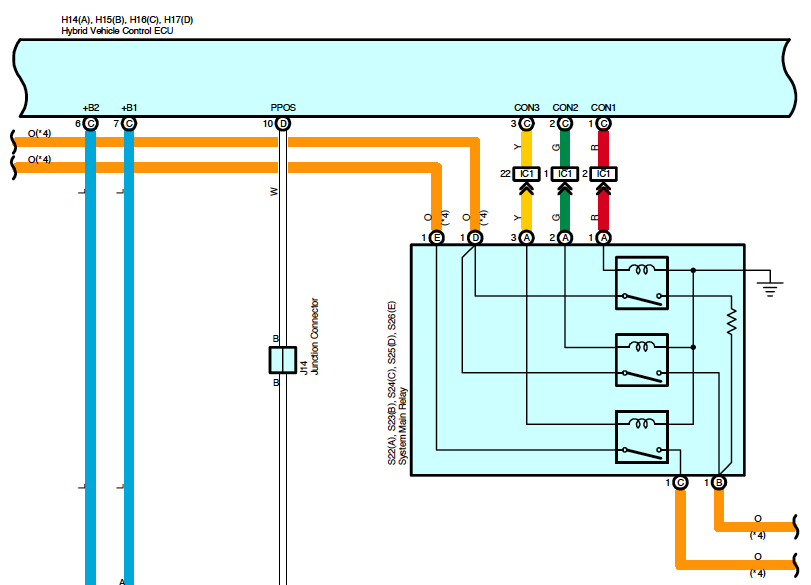
The High Voltage Battery has 3 contactors in the System Main Relay unit, as seen in Fig 2.1. These three contactors are controlled by the Hybrid Vehicle Control ECU at pins CON1, CON2 and CON3. This must also be intercepted by converter board.
Two contactors will also need to be added in order to connect and disconnect a motor and to connect the mains to the inverter also.
Microcontroller 💾
Pin requirements:
- 4 digital pins for selecting intercepts
- 5 digital pins for errors
- 3 digital pins for contactors
- 6 ADC pins for sensors
Digital pins: 12 Analog pins: 6
(Arduino nano)
- 11 digital pins
- 8 analog pins
Analog pins can be reused as digital pins.