VESC FOC

I wasn’t happy with the power that I was getting from the motor. Furthermore, it wasn’t as smooth as I would have liked. Field Oriented Control (FOC) can alleviate these problems. I have gone through the theory of FOC control in FOC control theory. There is also a good video by vedder himself on the topic: vedder video. The controller I am using is a Vedder Electronic Speed Controller or Vedder ESC or VESC, which is basically a standard ESC that is open source and developed by Benjamin Vedder.
Hall effect sensors 🔬
Hall effect sensors are used for position control. These sensors are particularly important for estimating rotor position when the motor is stationary. I think the VESC that I’m using uses Back EMF sensing at high speeds anyways because it’s more accurate. However, hall sensors work well independent of speed. When a pole is seen the output latches until the opposite pole is seen. I thought that these hall sensor ICs had a voltage output, but it actually acts more like a switch, so an external voltage must be applied to test them.
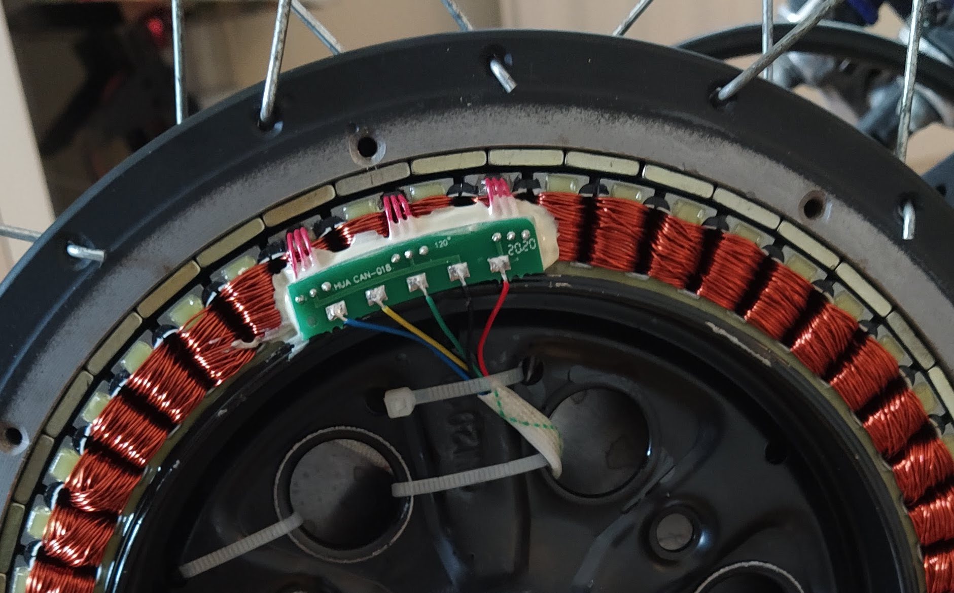
Long story short, just connect power ground and the three hall sensor wires to the VESC and you’re good to go 😅
BLDC tool setup ⚙️
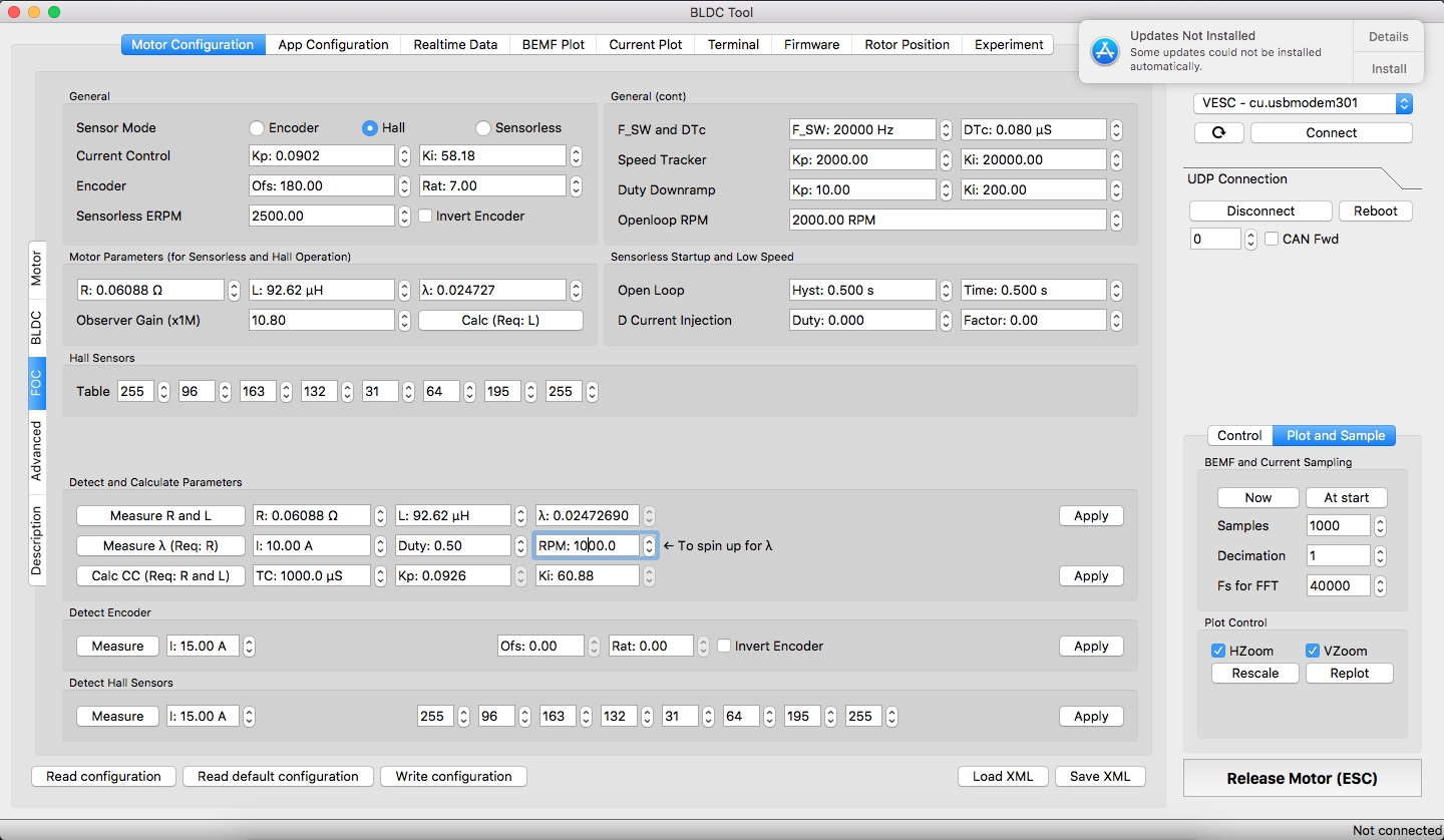
The steps for using the BLDC tool are as follows:
- Connect hall sensors
- Select hall sensors at top and click detect hall sensors
- the motor spins and detects their position
- Measure R (resistance) and L (inductance)
- used to compensate for the electrical characteristics of the motor
- the motor vibrates
- Measure lambda
- lambda is the flux linkage which indicates the concentration of the magnetic field inside the motor
- the motor vibrates and then spins up
- Calculate current control (CC) coefficients
- ki and kp are the PID Parameters
- Apply all measurements
Parameters
- Current control: Kp, Ki
- Speed tracker: Kp, Ki
- Duty downramp: Kp, Ki
- R (resistance of the motor coils)
- L (inductance of the motor coils)
- Lambda (flux linkage)
- Observer gain (observer is used to determine the angle of the rotor for FOC)
- F_SW (switching frequency of the PWM )
- DTc (deadband time) (if stays still for openloop hyst time it’ll run with openloop RPM for openloop time)
- Openloop RPM
- Open loop hyst
- Open loop time
- D current injection: Duty, Factor
- CC (current control loop)
Increasing power ⚡
The power was still limited after setting up FOC. I did a bit of testing. The BLDC tool has some nice graphing and data acquisition tools with it. So I tested the maximum power output in a stall.
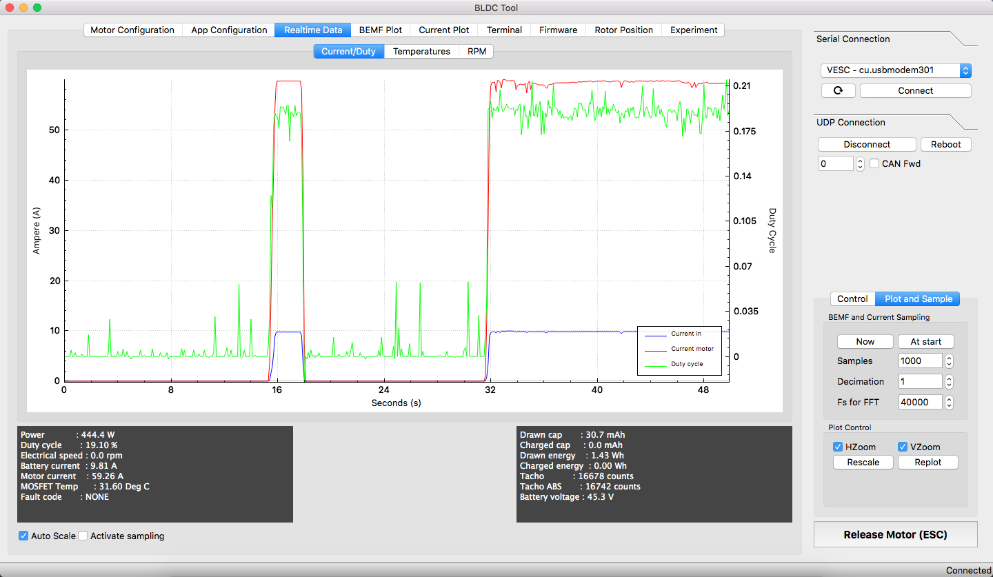
The problem was that the motor current was limited to 30 amps. Which means the maximum power was 30A*50V=1.5kW peak. This… is not enough 😈 I want more power!!! ⚡ So I increased the motor current limit to 60A which means the motor can now have peak power of 60A*50V=3kW. Much better 😊 I could have increased the limit even more, however the battery current limit was reached at 10A and I did not want to exceed 10A. I believe the motor current can exceed the battery current because the controller has large capacitors that store energy for when there is a peak in power consumption from the motor. This decreases stress on the motor.